Clark Labs Assists Local Town in the Siting of Cell Towers
Current US government regulations state that cellular phone companies have the right to install towers in any town where they perceive a market exists. Towns, in most cases, are willing to comply with this regulation, but many do not have access to the required technologies to perform the site selection themselves. These towns must defer the analysis to the cell phone companies. Recently, the small town of Paxton in Central Massachusetts approached the Clark Labs to assist them in doing their own analysis for cell tower location after having been approached by a cell phone company that wished to expand their services. A viewshed analysis was deemed the best approach to the problem. A combination of tools in TerrSet, including the VIEWSHED module, was employed for the analysis.
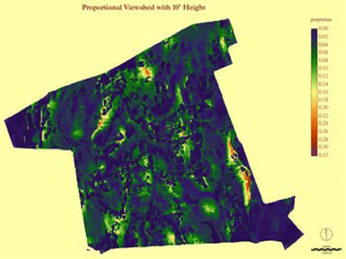
Typically, a viewshed analysis is done by predetermining view sights and running a viewshed analysis that outputs a Boolean image. A pixel is either in view or not in view based on the topography and the starting point and its height. Figure 1 shows such an output. The point in red is the inception point at a height of 10 feet. This is the highest point in town which is currently zoned for cell towers. Indeed, most of the cell towers in the town are located here. The area in blue shows those areas in the town of Paxton that are in view. Clearly much of the town is not covered for cellular service.
The difficulty with this particular approach to solving the siting of new towers is that if thousands of sites, or in our case pixels, are potential candidates, analysis can be quite time consuming. We decided on an alternative, less costly approach, the proportional viewshed option included with IDRISI. Using the entire town as the source image, every pixel is evaluated for the proportion that the rest of town, i.e., every other pixel, is in view.

Before utilizing the VIEWSHED module, we created a landuse map from our SPOT image and adjusted certain heights based on the landuse categories. Since cell phone technology is affected by line-of-sight, the elevation in forest cover and residential areas was increased to account for the tree canopies and roof lines. We then classified the scene (Figure 2) into four relevant landuse categories: open, forest, residential and ponds. We then

assigned new uniform heights of 50 feet for forest and 30 feet for residential areas to selectively raise the elevations on the elevation model.
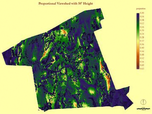
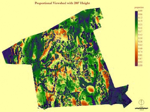
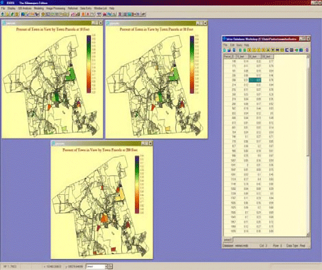
We then input this elevation model into the VIEWSHED module. Figures 3, 4 and 5 show the result of proportional viewsheds given different viewer heights of 10, 50, and 200 feet.
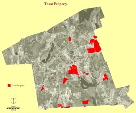
At this point, we needed to incorporate the criteria for the site selection. One of the requirements for the town is that all tower installations must be on town property. Figure 6 is a parcel map of the town with town property parcels shown in red. Figure 7 shows the maximum proportion of each parcel at different viewer heights.
Several of the properties stand out as potential sites. But the town also decided to impose another requirement, that any proposed towers be at least 100 feet from residential areas.
To combine all of this information, we needed to use the MCE (Multiple Criteria Evaluation) module (Figure 8). There we specified the input factors to be the distance from residential areas as well as the proportional viewshed result itself. The one constraint used was the town boundary. Finally, we specified the use of OWA and used weights of 1 and 0, in that order. This is the minimum, low risk operator. The minimum operator was chosen in order to compensate for areas that may be highly suitable for their viewshed but were also very near to residential areas.
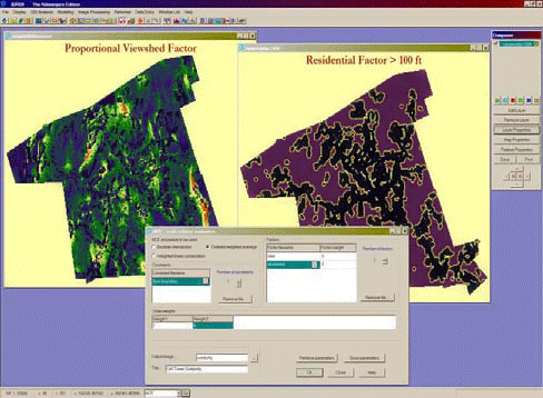
Tradeoff is the degree to which one factor can compensate for another; how they compensate is governed by a set of factor weights sometimes called tradeoff weights. In addition to tradeoff, any MCE is also characterized by some level of assumed risk that will strongly influence the final suitability map. A low risk analysis is one where the area considered most suitable in the final result is minimized since it must be highly suitable in all factors. A high risk analysis is one where the area considered most suitable in the final result will be maximized since any area that is highly suitable for any one factor will be considered highly suitable in the result. The OWA option in MCE models this tradeoff and risk.
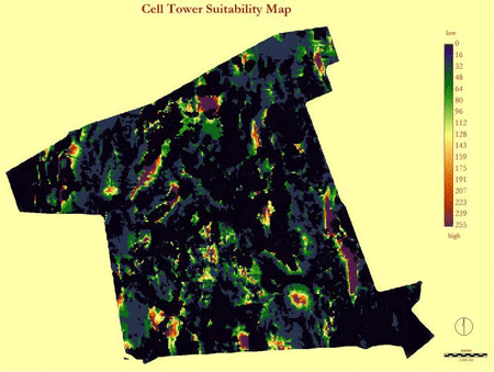
Figure 9 shows the final suitability map for those areas resulting from the MCE.